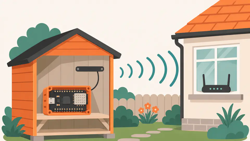
An ESP32-S3 project that works on the desk can drop off the network once it is boxed up and mounted in the shed. The board has not changed. Its surroundings have: there is now a wall, a case and perhaps a sheet of steel between the antenna and the router.
This guide shows how to measure the signal, what to fix first, and when an external antenna is worth the extra work. It is written for the ESP32-S3 N16R8 development board, which has both an on-board antenna and a connector for an external one.
Measure before you change anything
Guessing at Wi-Fi problems wastes time. The board can report its received signal strength, called RSSI, in dBm. The number is negative, and closer to zero is stronger.
This sketch connects to your network and prints a reading every second, with an average every 30 readings.
// Wi-Fi signal logger for comparing antenna and enclosure options on an ESP32-S3.
// Prints one RSSI reading per second, plus a 30-reading average.
#include <WiFi.h>

const char* WIFI_SSID = "your-2.4GHz-network";
const char* WIFI_PASSWORD = "your-password";

const int SAMPLES = 30;
long total = 0;
int count = 0;

void setup() {
  Serial.begin(115200);
  delay(1500);
  WiFi.mode(WIFI_STA);
  WiFi.begin(WIFI_SSID, WIFI_PASSWORD);
  Serial.print("Connecting");
  while (WiFi.status() != WL_CONNECTED) {
    delay(500);
    Serial.print(".");
  }
  Serial.printf("\nConnected to %s on channel %d\n", WiFi.SSID().c_str(), (int)WiFi.channel());
}

void loop() {
  if (WiFi.status() != WL_CONNECTED) {
    Serial.println("Wi-Fi lost, waiting to reconnect...");
    delay(1000);
    return;
  }
  int rssi = WiFi.RSSI();
  total += rssi;
  count++;
  Serial.printf("RSSI: %d dBm\n", rssi);
  if (count == SAMPLES) {
    Serial.printf("Average of %d readings: %.1f dBm\n", SAMPLES, (float)total / SAMPLES);
    total = 0;
    count = 0;
  }
  delay(1000);
}
Single readings jump around, so compare the averages. As a rough rule of thumb:
| Average RSSI | What to expect |
|---|---|
| Above −60 dBm | Strong. No changes needed. |
| −60 to −70 dBm | Good for sensor data and small web pages. |
| −70 to −80 dBm | Marginal. Expect occasional drop-outs and slow reconnections. |
| Below −80 dBm | Unreliable. Improve the placement or the antenna. |
These bands are a guide, not a specification. A sensor that sends one small reading every few minutes tolerates a weaker signal than a device streaming audio.
A fair test
Change one thing at a time and record the average for each step:
- The bare board on the desk near the router, as a baseline.
- The bare board at the place where the project will live.
- The board inside its case, at that same place and in the same orientation.
The difference between steps 1 and 2 is the building. The difference between steps 2 and 3 is the case and how the board sits in it. That tells you which problem you have.
What blocks Wi-Fi, and what does not
The ESP32-S3 uses 2.4 GHz Wi-Fi only. That band passes through timber framing and plasterboard fairly well. It is stopped or weakened by:
- Metal. Long-run steel roofing and cladding, a steel shed, a metal switchboard cabinet or a fridge.
- Foil-backed insulation and building wrap.
- Concrete, concrete block and brick, more so when damp or reinforced.
- Water, including a full water tank between the board and the router.
Plain PETG is not on that list. A couple of millimetres of unfilled plastic makes little difference to a 2.4 GHz signal. The exceptions are filaments filled with carbon fibre or metal powder, which are best kept away from the antenna.
So when a printed case seems to hurt the signal, the cause is usually something that came with the case: a metal mounting plate, screws beside the antenna, a battery laid across it, or a new position against a steel wall.
Fix the placement first
These cost nothing and often recover more signal than new hardware:
- Keep the antenna end clear. On the board, the antenna is the patterned area at the end of the module. Leave a gap around it, with no screws, wires, batteries or metal brackets beside or behind it.
- Do not mount the board flat against metal. Use a printed standoff or bracket to space the case away from a steel surface.
- Raise it. A metre of extra height often clears furniture and appliances.
- Turn it. Rotating the case by 90 degrees can change the reading noticeably. Try each orientation and keep the best.
- Look at the router end. Moving the router out of a cupboard, or adding a mesh node nearer the project, helps every device at once.
When you design the case, decide where the antenna end goes before anything else. Our PETG enclosure design guide shows how to describe that to an AI coding agent as a design rule.
When to use an external antenna
If the signal is still marginal after the placement fixes, or the board has to live inside a metal box, an external antenna lets you put the radiating part where the signal is while the board stays where it is convenient.
The 5dBi FPC antenna with an IPX connector we stock is a flat, flexible strip with an attached coaxial lead. The antenna element measures 50 × 14 mm. The 5 dBi figure is the supplier’s rated gain; what you get in practice depends on where and how it is mounted, which is another reason to measure.
Two things to know before fitting one
The board needs a small hardware change. According to the supplier’s hardware notes, this board uses its on-board antenna by default, and using the external connector requires changing the antenna-selection resistor configuration. That means moving a very small surface-mount part with a fine-tipped soldering iron. If you are not comfortable with that, the placement fixes above are the better route. Follow the instructions for your exact board, and see the board’s hardware notes.
The connector is delicate. Check that the antenna’s plug matches your board’s socket before ordering. Press it on straight and gently, and avoid connecting and disconnecting it more than you need to.
Once the board is set to use the connector, always run it with an antenna attached.
Mounting an FPC antenna in a printed case
- Give it a flat area at least 50 × 14 mm on the inside of a lid or wall. PETG is a good surface for it.
- Keep it away from metal, batteries and wiring looms, and away from the board itself where the case allows.
- Do not crease the element, and route the lead in gentle curves without sharp bends.
- Fix the lead with a printed clip so that movement does not pull on the connector.
- For a board inside a metal enclosure, the antenna has to sit outside the metal, under a plastic cover.
Then run the signal logger again, in the same place and orientation as before, and compare the averages. If the number has not improved, try the antenna in a different position before concluding it does not help.
A realistic expectation
An antenna does not create signal. It changes how well the board hears the signal that reaches it and where the sensitive part sits. A change of a few dB can turn a marginal link into a dependable one. It will not carry Wi-Fi through a steel shed wall, or across a paddock, without help at the router end, such as an access point nearer the project.
For a tank, a gate or a shed that is simply too far away, a Wi-Fi access point or mesh node closer to the project is usually a better fix than a bigger antenna on the board.
Related guides
- ESP32-S3 N16R8 getting-started guide: board setup and the pins to leave alone.
- Design a PETG enclosure with AI and OpenSCAD.
- Seven ESP32-S3 project ideas for NZ homes, including a rainwater tank monitor where range matters.
- Write, flash and debug firmware with Claude Code.
Browse the ESP32-S3 boards, antennas and cables we stock in Auckland, with New Zealand delivery or free pickup in Torbay.
How this guide was put together. It was drafted with AI assistance. Antenna and board details come from our product listings, and the sketch was compiled against version 3.3.12 of the ESP32 Arduino package. We have not published range measurements because results depend on each building; the signal bands above are a general rule of thumb. This article is not a current stock list: check the ESP32-S3 range and the live PETG catalogue for current products, prices and stock.