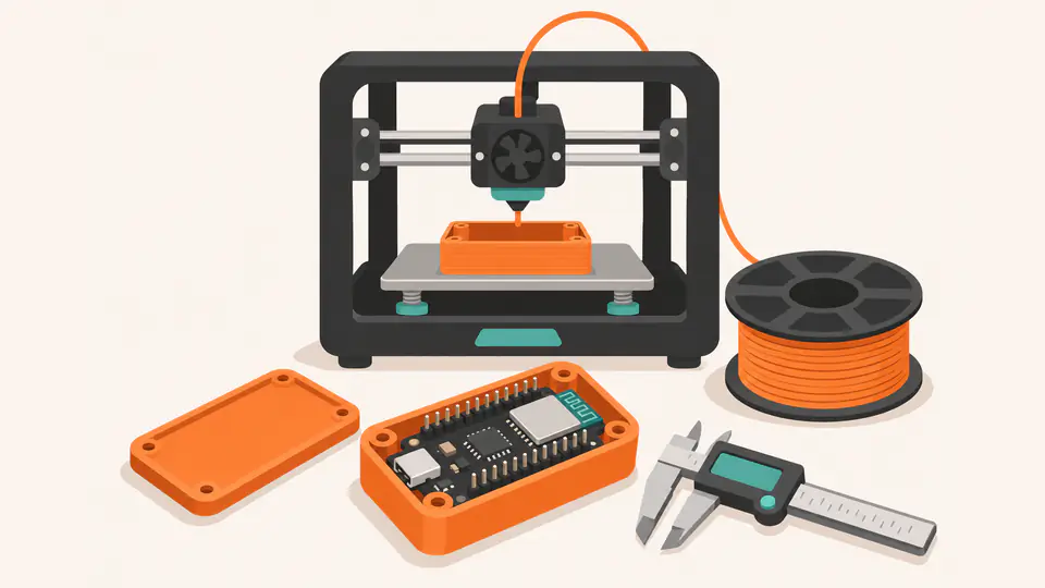
A bare development board on a desk is a prototype. The same board in a case that fits it is something you can mount in a shed, hand to someone else or leave running for a year. This guide shows a way to get from one to the other: measure the board, describe the case in words, let an AI coding agent write a parametric model, and print it in PETG.
The method works for any small board. The examples use the ESP32-S3 N16R8 development board with pre-soldered headers.
Why a code-based CAD tool suits AI
AI agents write text. Most CAD programs store drawings as mouse actions in a binary file, which an agent cannot usefully read or edit. OpenSCAD is different: a model is a short text file of dimensions and shapes, and one command turns it into a printable STL.
openscad -o tray.stl tray.scad
openscad -o tray.png --imgsize=1200,900 tray.scad
That gives an agent such as Claude Code the same build-and-check loop it uses for firmware, described in our firmware workflow guide. It edits the file, renders it, reads any errors and looks at the preview image. Because every size is a named variable, changing a clearance by 0.1 mm is a one-line edit and not a redraw.
Step 1: Measure the board you actually have
Do not design from a photo or from dimensions found online. Boards that look alike differ by a millimetre here and there, and a millimetre is the difference between a fit and a reprint. Our listing does not publish a mechanical drawing, so measure your own board with calipers and write the numbers down:
- PCB length, width and thickness.
- How far the header pins hang below the PCB.
- The width of the strip along each long edge that the header rows occupy.
- Each USB-C connector: its width, its height above the PCB and the distance of its centre from the board’s centre line.
- The tallest component on top, and where the antenna end of the module sits.
If your board will sit on a 44-pin terminal breakout board, measure the assembled pair instead, including the height of the screw terminals and the room a screwdriver needs to reach them.
Step 2: Describe the case
A good request states what the case must do, gives every measurement and names the constraints of the printer. For example:
Write an OpenSCAD file for an open-top tray that holds a headered ESP32-S3 board. The PCB is 57 × 28 × 1.6 mm and the header pins hang 9 mm below it. Support the PCB on a ledge at each end, between the two header rows. Leave notches in one end wall for two USB-C plugs, centred 7 mm either side of the centre line and 10 mm wide. Add a slot in one long wall for jumper wires. Use 2 mm walls and 0.3 mm clearance per side. Make every dimension a named variable. It will be printed in PETG with a 0.4 mm nozzle, flat on its base, without supports. Render it to an STL and a PNG and check both.
Those measurements are placeholders for the example. Use your own.
A working example
This is the kind of file that request produces. It renders as a single solid about 62 × 33 × 14 mm with the example values.
// Parametric tray for a headered ESP32-S3 development board.
// EXAMPLE VALUES ONLY: measure your own board with calipers and replace them.
board_l  = 57;     // PCB length, mm
board_w  = 28;     // PCB width, mm
board_t  = 1.6;    // PCB thickness, mm
pin_drop = 9;      // how far the header pins hang below the PCB, mm
row_keepout = 6;   // strip along each long edge kept clear for the header rows, mm
fit      = 0.3;    // clearance per side, mm
wall     = 2;      // wall thickness, mm
floor_t  = 1.6;    // floor thickness, mm
ledge    = 3;      // depth of the end ledges that support the PCB, mm
rim      = 2;      // wall height above the top of the PCB, mm
usb_w    = 10;     // USB-C opening width, mm
usb_centres = [-7, 7];  // opening centres measured from the board centre line, mm

inner_l = board_l + 2 * fit;
inner_w = board_w + 2 * fit;
depth   = pin_drop + board_t + rim;

difference() {
  cube([inner_l + 2 * wall, inner_w + 2 * wall, floor_t + depth]);
  // cavity for the board and its header pins
  translate([wall, wall, floor_t]) cube([inner_l, inner_w, depth + 1]);
  // USB-C notches in the end wall, starting at the top surface of the PCB
  for (c = usb_centres)
    translate([-1, wall + inner_w / 2 + c - usb_w / 2, floor_t + pin_drop + board_t])
      cube([wall + 2, usb_w, rim + 1]);
  // slot in one long wall for jumper wires
  translate([wall + inner_l / 2 - 8, -1, floor_t + 1]) cube([16, wall + 2, pin_drop - 2]);
}

// end ledges: the PCB rests on these, between the two header rows
for (x = [wall, wall + inner_l - ledge])
  translate([x, wall + row_keepout, floor_t]) cube([ledge, inner_w - 2 * row_keepout, pin_drop]);
Before printing anything from a generated file, check three things yourself: the overall size makes sense for your board, the USB notches are on the end where your USB ports are, and nothing solid sits where a component or a header pin needs to be.
Step 3: Print a fit test first
Do not print the whole case to find out that a notch is 1 mm off. Ask the agent for a fit coupon: the first few millimetres of the tray plus the end wall with the USB notches. It prints in minutes, uses very little filament and answers the questions that matter:
- Does the board drop in without force and without rattling?
- Do the USB plugs seat fully through the notches?
- Do the header pins clear the ledges?
Feed the result back as numbers, such as “the board is tight by about 0.2 mm on the width” or “the left notch needs to move 1 mm outwards”. The agent changes the variables and renders again. Expect a couple of rounds before the fit is right.
Design rules that suit PETG
PETG is a practical choice for enclosures because it has some give: clips and thin walls tend to flex where a more rigid material might crack. We compare the two materials in PETG vs PLA. These starting points are worth putting in your request:
- Walls in whole multiples of the nozzle width. With a 0.4 mm nozzle, 1.6 mm or 2 mm walls print as clean, solid perimeters.
- Clearance of about 0.2 to 0.3 mm per side for a part that should drop in. Printers differ, which is why the fit coupon matters.
- Chamfers, not overhangs. A 45° chamfer under a lip prints without supports; a flat overhang sags.
- Rounded inside corners on anything that flexes, such as a clip or a snap-fit lid. Sharp corners concentrate stress.
- Vents if anything inside gets warm. A few slots above and below the board let air move through.
- Mind the build plate. PETG can bond strongly to some build surfaces, so follow the plate maker’s guidance, and see our PETG bed adhesion guide.
For the print itself, use the settings on your spool’s label as the starting point: our PETG print settings guide explains how to find them. Stringing inside small cut-outs is often a sign of damp filament, covered in why and how to dry filament.
Leave the antenna some room
The Wi-Fi antenna is the part of the design that is easiest to get wrong without noticing.
- Plain PETG is not a meaningful barrier to Wi-Fi. Metal is. Keep screws, brackets, batteries and foil labels away from the antenna end of the board.
- Avoid carbon-fibre and metal-filled filaments for the wall beside the antenna.
- If the case sits against a metal surface, put the antenna end furthest from it.
When a build needs more range than the on-board antenna gives, a flat 5dBi FPC antenna with an IPX connector can be stuck to the inside of a lid or wall. Its element measures 50 × 14 mm, so give it a flat area at least that size, away from metal. Using the board’s external antenna connector needs a small hardware change first, which we explain in ESP32-S3 Wi-Fi range in a 3D printed case.
Other things worth printing
- A stand or wall dock for the voice assistant. The assembled ESP32-S3 Wi-Fi AI voice assistant comes in a clear enclosure measuring 41 × 41 × 30 mm. A printed cradle that tilts the screen towards you, with a channel for the USB-C cable, is a good first parametric design because there is only one box to fit.
- A sensor pod. A small vented cap on a short lead keeps a humidity sensor away from the warmth of the board. Our filament dry-box monitor uses that layout.
- A DIN-rail or screw-mount base for the board on its terminal breakout.
A note on outdoor use
PETG generally tolerates more warmth than PLA, and finished PETG prints resist moisture well, but a printed case is not weatherproof by itself: layer lines and lid joints let water in. For anything outside, add a gasket or mount the case under cover with the openings facing down. Parts that sit in strong New Zealand sun for long periods may need a material made for UV exposure, or a coat of paint.
Pick a colour and print
A small enclosure uses only a fraction of a 1kg roll, so colour is mostly a matter of taste. Our guide to choosing PETG filament covers solid, marble and multicolour options, and a transparent PETG lets a status LED show through the case.
Next in this series: build a filament dry-box humidity monitor, then browse seven ESP32-S3 project ideas for NZ homes.
How this guide was put together. It was drafted with AI assistance. The example file was rendered with OpenSCAD to confirm it produces a single valid solid, but it was not printed or fitted to a board before publishing, and its dimensions are placeholders. Measure your own hardware. This article is not a current stock list: check the ESP32-S3 range and the live PETG catalogue for current products, prices and stock.